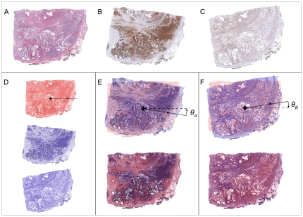
Figure 4. Alignment results using TurboReg.
(A) Image of H&E-stained reference section image. (B) Image of section stained for ACPP previously brought into rough alignment with reference image by user. (C) Image of section stained for ENO2 previously brought into rough alignment with reference image by user. (D) Monochromatic images of A–C generated for purposes of overlay illustrations. (E) TurboReg translated and rotated (angle ⊖A) the image of ACPP-stained section until a mean location error was minimized. (F) Similarly, TurboReg translated and rotated (angle ⊖B) the image of ENO2-stained section to minimize mean location error between this image and the reference H&E-stained image. The final registered IHC image is overlaid on the reference H&E image in the bottom of panels (E) and (F). Values for translations and rotation determined by TurboReg along with the initial coarse registration steps were stored in the software for later use in transforming grid locations from the reference to the IHC images when generating IHC and signature maps.

