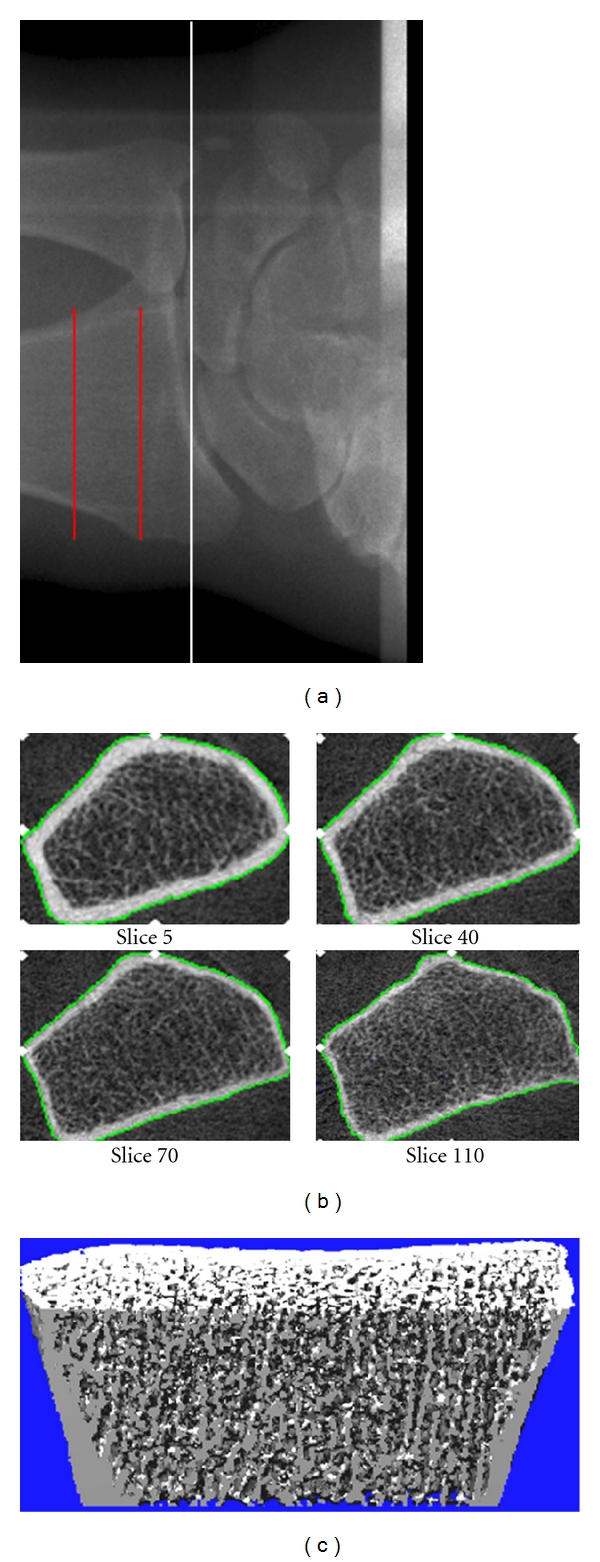
Figure 1.

(a) Radiograph showing the site of imaging by HR-pQCT at the distal radius. The white line indicated the proximal level of the joint space, and the red lines indicate the section of bone over which images are acquired. (b) Representative cross-sectional images from the stack of CT slices. (c) Representative 3D image. Images were obtained using the initial prototype of the HR-pQCT scanner (Figure is reprinted with permission from Khosla et al. [8] ©2006 American Society for Bone and Mineral Research).
