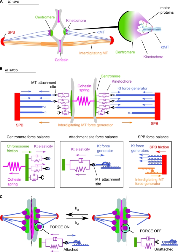
Figure 1.
Schematic representation of the metaphase spindle. (A) In vivo. (left) The two SPBs are linked by overlapping interdigitated microtubules (MT). The chromosome (gray) is linked to the SPBs by its centromere regions. The four microtubule attachment sites located on each kinetochore (Kt) are connected to the SPBs by ktMTs. The two sister chromatids are held together by the cohesin complex. (right) Schematic depiction illustrating the in vivo structure of the ktMT attachment site. Several motors are present at the ktMT interface. (B) In silico. (top) The SPBs are linked by the interdigitated microtubule force generator. Each microtubule attachment site on the kinetochore is linked to the SPB through a ktMT (blue). The four microtubule binding sites (purple) are associated to the chromosomes by the centromere and represented by a spring and a dashpot (purple). Cohesin between the sister chromatids is modeled as a single spring linking both centromeres. (bottom) Schematic depiction illustrating the different forces applied in silico at the centromere level (left), the microtubule attachment site (middle), and at the SPB (right). (C) A simple stochastic process of microtubule attachment and detachment reproduces the directional instability. At any time, microtubule attachment sites (purple) attach with the frequency ka (left, force is on) or detach with the frequency kd (right, force is off). This attachment/detachment process leads to an imbalance of the forces applied on the chromosome and to chromosome dynamics within the spindle (also see Video 1).

