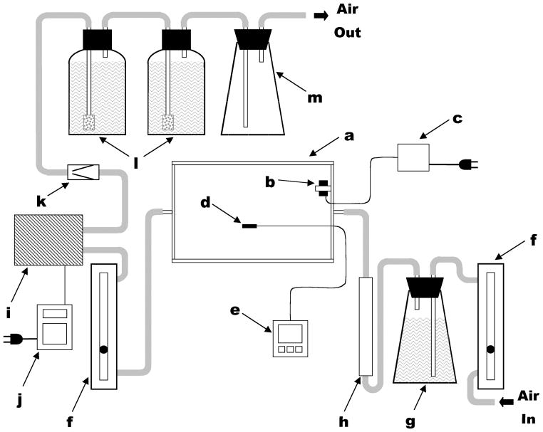
Figure 1.
Schematic representation of complete enclosed-chamber labeling system. Components (not drawn to scale) include: (a) polyacrylic chamber; (b) 12 V DC circulating fan; (c) 12 V DC power supply; (d) temperature probe; (e) data logger; (f) adjustable gas flow meters; (g) flask with NaOH and air tubes; (h) water vapor absorbent column; (i) air pump; (j) programmable timer; (k) one-way safety valve; (l) screw-capped bottles with NaOH and fritted-glass air bubblers; (m) aerosol trap. Components used in air handling were connected using flexible plastic tubing (indicated in gray). Reprinted from Grusak et al. In Vitro Cell Devel Biol Plant 2004, 40:80–85 by the Society for In Vitro Biology. Reproduced with permission of the copyright owner.

