. Author manuscript; available in PMC: 2013 Apr 5.
Published in final edited form as: J Biomech. 2012 Jan 28;45(6):1117–1122. doi: 10.1016/j.jbiomech.2011.12.025

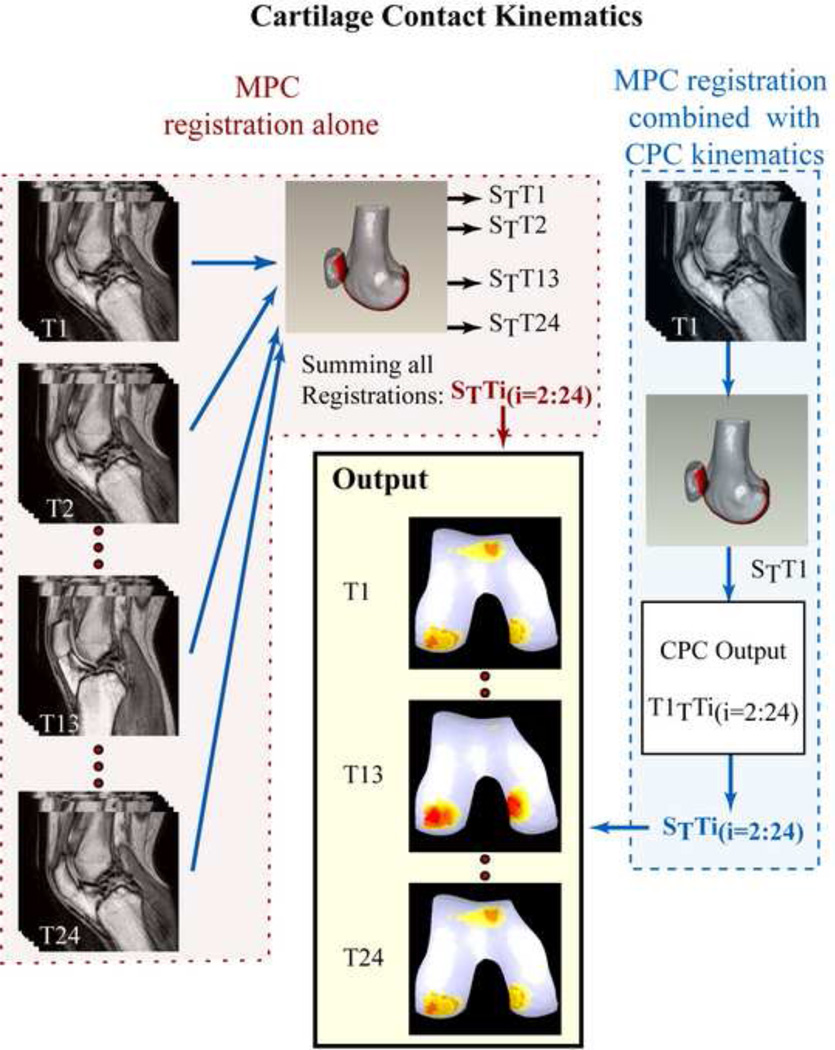
Figure 3. Quantifying Cartilage Contact Kinematics.

Figure 3

Two methodologies (MPC registration in isolation and MPC registration combined with CPC kinematics) could apply the knee joint kinematics to the static bone and cartilage surfaces in order to calculate contact kinematics. The first methodology delineated the bone of interest in each of the MPC images and then registered each dynamic time frame to the static model (Left column registered to center 3D model):
TTiS,i=1:24
STTi, the transformation matrix defining the transformation from a single dynamic time frame to the static model.
The kinematics of the bones were known based on the integration of the CPC data (TnTTi, i=2:24, n = reference time frame). Thus, the location of the bone and cartilage surfaces was known throughout the motion cycle once the registration of a single dynamic time frame to the static model was completed (STTn, Right column), through matrix multiplication:
TTiS=TTnS*TTiTn
The output of both techniques (bottom, center column) is the position of the bone and cartilage surfaces throughout the dynamic motion. Denoted on the femoral cartilage surfaces are the contact areas of the patella and tibia.