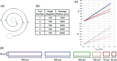
Figure 2.
This is (a) a schematic of the device design and its (b) dimensions. The (c) channel Reynolds number and average Dean number are given as a function of average downstream velocity. Each line represents a different channel width increasing from bottom to top (50 μm bottom line to 400 μm top line). (d) Cross-sectional views of the channels utilized are also shown.

