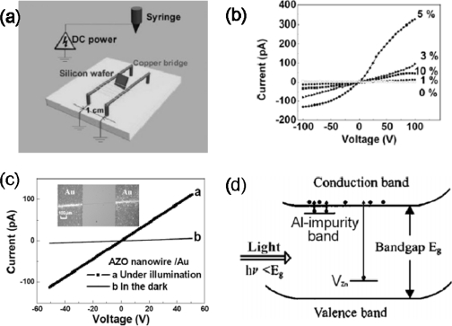
Figure 3.
(a) Schematic illustration of the setup used for electrospinning nanowires as uniaxially aligned arrays; (b) The measured current-voltage (I–V) curves of undoped and Al-doped samples; (c) Photoresponse of the Al-doped ZnO nanowires (1 at% Al) to below-gap illumination (Au electrodes); (d) Schematic energy band diagram of the photoswitches. Reproduced from [20].

