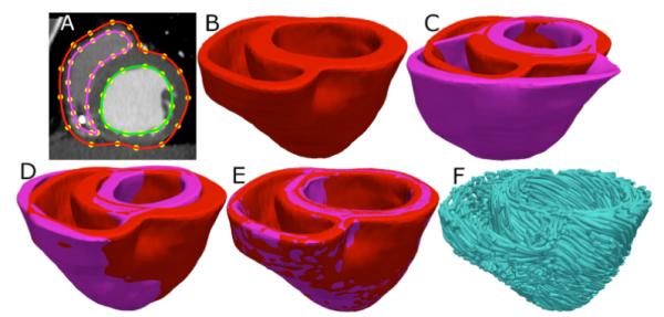
Fig. 2.

Application of the fiber orientation estimation methodology to an example patient heart image. (A) The epicardial (red) and endocardial (green and magenta) splines, and corresponding landmarks (yellow) overlaid on an image slice. (B) patient ventricles in 3D. (C) Superimposition of ventricles of atlas (magenta, see Fig. 1B) and patient. (D) Patient ventricles and the affine transformed atlas ventricles. (E) Patient ventricles and LDDMM-transformed atlas ventricles. (F) Estimated patient ventricular fiber orientations.
