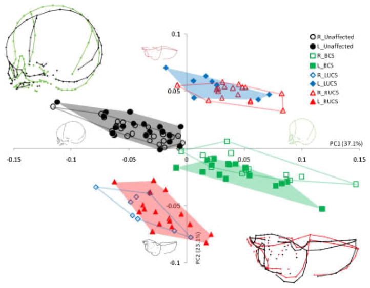
Figure 7.
Placement of the half-skulls on PC1 and PC2 in the shape space after adjusting for allometry. Different convex hulls are drawn for the left and right bicoronal, left unicoronal, right unicoronal, and unaffected half-skull. Wireframe graphs representing the shape changes associated with positive and negative values of PC1 in lateral view and the shape changes associated with positive and negative values of PC2 in superior view are represented for each PC and superimposed in the top left corner and the bottom right corner, respectively.

