
Figure 1.
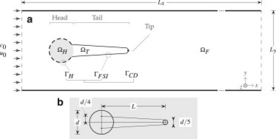
(a) Schematic representation of the two-dimensional subdomains and boundary conditions: ΩH, biofilm head subdomain; ΩT, biofilm streamer tail subdomain; ΩF, fluid subdomain; Γ, interface between biofilm and fluid. At the inlet boundary c0 is the constant substrate concentration and u0 is the fluid velocity. The center of ΩH is located at x = y = 1.5 × 10⁻³ m. (b) Geometric construction of the biofilm streamer.