
Figure 1.
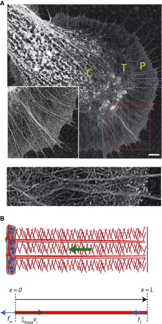
Actin treadmill in the nerve growth cone. (A) Upper, Electron microscopy image of an Aplysia bag cell nerve growth cone, obtained as described in Schaefer et al. (40). (Inset) Higher magnification of P domain (larger box), showing the dendritic network of veil filaments interspersed with filopodial bundles. The central (C) domain, transition (T) zone, and peripheral (P) domain are labeled. Scale bar, 3.5 μm. Lower, Higher magnitude of quasi-1D slice of P domain (smaller box in upper image), to illustrate a representative region of interest for the 1D model illustrated in B. (B) Upper, Schematic of the actin treadmill components: actin filaments (center), leading edge (right), and T zone and myosin (left). The actin network undergoes retrograde flow (green arrow). Lower, balance of forces in the 1D model for the P-domain actin network. The coordinate x represents the distance from the boundary between the T zone and P domain, with x = L corresponding to the leading edge. The active forces driving retrograde flow are membrane tension, fT, and myosin contraction, fm (arrows pointing to the left). The effective drag force opposing retrograde flow (arrow pointing to the right) arises from the necessity to disassemble the actin network at the T zone.