
Figure 1.
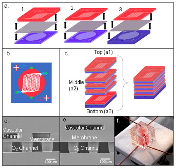
a) A schematic of the transfer module assembly alignment. In each case, the oxygen channel piece (blue) is bonded to the membrane (purple) first, and then aligned to the vascular channel piece (pink). This process is done for the top transfer module (1.), each middle transfer module, comprised of thin oxygen and vascular channel pieces (2.), and the bottom transfer module (3.). b) A schematic of a middle post-alignment transfer module shows hole-punching sites marked by purple dots. c) The entire device is built by assembling each individual transfer module first, then bonding all of the layers together in an alternating manner. d) An SEM image of a cross section of a transfer module comprising a 50 μm deep vascular channel network on the top, a 30 μm thick membrane, and a 100 μm deep oxygen channel on the bottom, where support posts can be seen throughout the channel. e) An SEM image of a cross section of a transfer module comprising a 50 μm deep vascular channel network on the top, a 117 μm thick membrane, and a 100 μm deep oxygen channel on the bottom. f) A 10-transfer module (10-TM) oxygenation device shown filled with blood in the vascular channel.