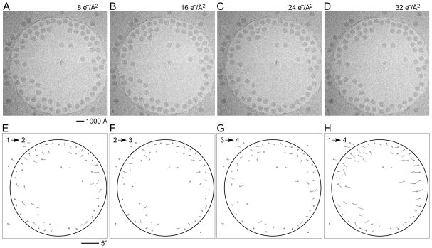
Figure 1.
Exposure series of rotavirus DLPs in ice in a C-flat™ 1.2/1.3 grid (hole size = 1.2 μm). Four successive exposures are shown in panels A, B, C and D. The total dose applied to the sample is noted above each exposure. Panels E, F and G show vector plots corresponding to the changes in particle orientations between exposures (exposure numbers are indicated in the plots). Panel H plots the summed vectors from panels E, F and G.

