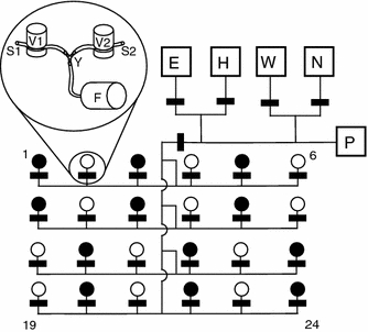
Fig. 1.

Pump and tubing system of the 24-feeder array. Lines represent the tubes, and black rectangles the pinch valves. Feeders are numbered 1–24. Boxes represent the following liquid reservoirs: ethanol (E), water (H), waste (W), nectar (N), and stepping-motor syringe pump (P), as described in Winter and Stich (2005). Length of tubes not drawn to scale. Two identical tubing systems were connected to the feeders. The merging point of the tubing systems is illustrated in the inset: magnetic pinch valves for the first (V1) and second tubing systems (V2), with their corresponding tubes (S1 and S2), a Y connector (Y) and feeder head (F). Feeders represented by black circles only received nectar from S1, and feeders shown in white were only fed by S2. The two pumping systems were filled with different sugar concentrations on different days. See “Methods” for further details
