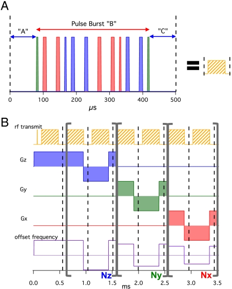
Fig. 1.
Schematic of our imaging sequence. (A) The main pulse block used in our imaging sequences with 90° (thin) and 180° (thick) pulses along the Y (green), X (red), and -X (blue) directions. (B) Diagram depicting the 3D MRI sequence with our pulse block where the loop counters: Nz, Ny, and Nx determine the k-space trajectory. The offset frequency can be set for each loop to place the image center off-center in the FOV. A single k-space point is sampled at each dashed line.

