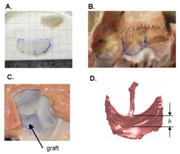
Figure 4.

(A) Height and free edge width of leaflet graft were based on dimensions of excised non-coronary leaflet, with the unstressed state determined by floating leaflet on a thin layer of PBS. (B) Graft (middle leaflet) sewn to the noncoronary root. Note that this photo was taken after CT imaging, as axial incision of the aorta was necessary to acquire this view. (C) Left ventricular surface of the pressure-loaded aortic valve after the noncoronary leaflet was replace with a graft. (D) Surface rendering of a CT scan of repaired valve loaded with pressurized air at 80 mmHg. The minimum central coaptation height of repaired valve was determined by manually delineating the central coaptation height, h, on each of the three leaflets then choosing the minimum. All four panels correspond to one of the surgical repairs in which both graft height and free edge width were 25% greater than the native leaflet that was excised (case W25H25).
