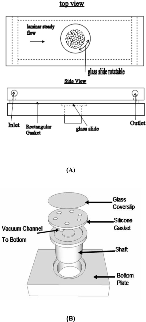
Figure 1.
Schematic of the flow system. (A): Diagram of the flow system. Rectangular flow channel is formed by a gasket held tight between top and bottom plate. Round glass slides are positioned in line with the bottom plate surface, and can be rotated by rotating the shafts; (B): Rotating mechanism. The vacuum line is connected from the bottom of the shaft to the vacuum channel. The shafts fit into holes very tightly to avoid leakage.

