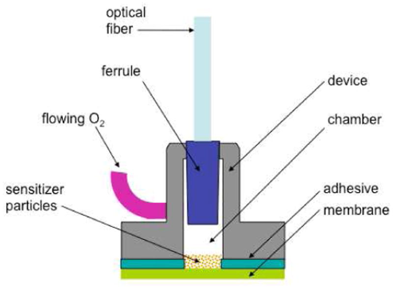
Figure 1.

Geometry of the 1O2-sparging photogenerator. At the top is the optical fiber leading from the diode laser, and at the left is the O2 feed tube, connected to an oxygen gas tank. The lower part of the device, which contains a chamber for stockpiled silicon phthalocyanine sensitizer particles, was sealed with a microporous membrane.
