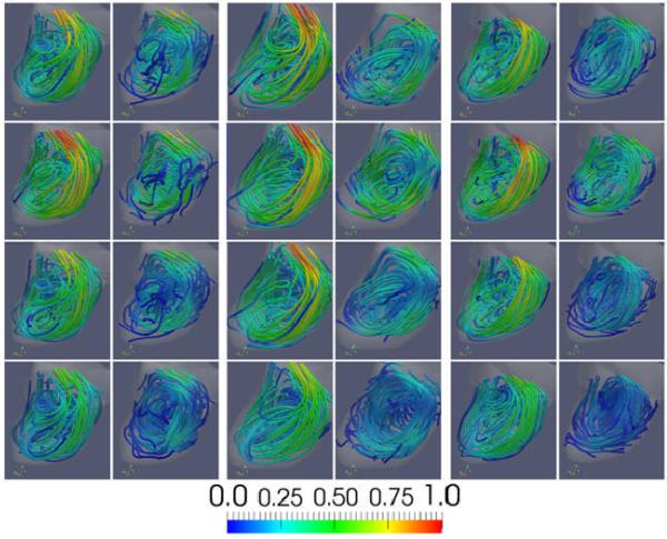
Figure 5.
: Visualizations of the aneurysmal blood flow pattern. The panels from left to right show the flow pattern at the three time points during the evolution of the aneurysm (corresponding to models M1, M2, and M3 of Figure 2). The left column of each panel shows the CFD flow field, while the right column the PIV flow field. The four rows show the flow fields at four instants of time during the cardiac cycle (time 1, 2, 3 and 4 of Figure 4).

