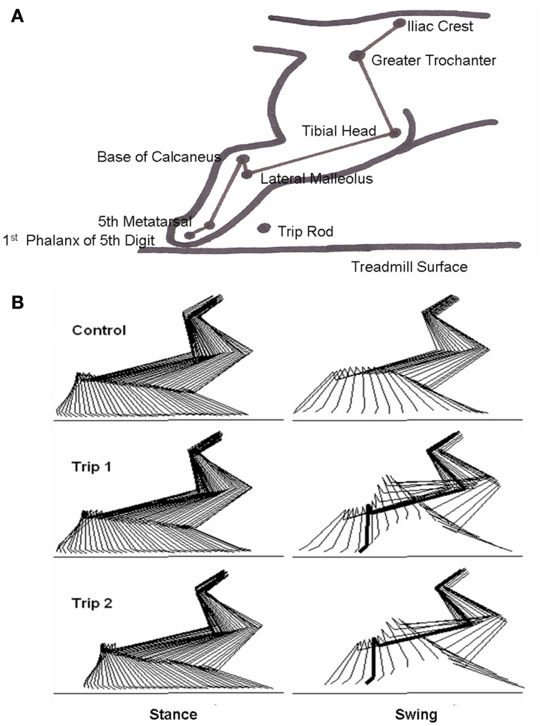
Figure 1.
(A) Schematic showing the bony landmarks in the cat hindlimb used for kinematics analyses, the position of the trip rod, and the treadmill surface. (B) Representative stick diagrams (17 ms between sticks) showing the stance and swing phases for a pre-trip (Control) step and the first (Trip 1) and second (Trip 2) trip steps. The horizontal lines denote the surface of the treadmill. The thick lines in the stick diagrams during Trip 1 and Trip 2 indicate the frame when the foot touches the trip rod during the swing phase.

