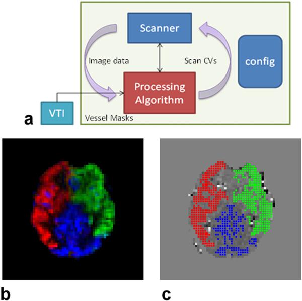
Figure 2.
(a) Schematic of the pre-scans. The VTI sequence (box in cyan) reads in the location of the tagging plane and coordinates of the major feeding arteries from the configuration file. The post processing routine at the end of the scan automatically generates the binary territory masks in panel (c), which are passed onto the post-processing script (red box) associated with the MP-PCASL scan. Using the image data from the MP-PCASL scan and the binary territory masks, this script calculates the global RF phase term and in-plane gradient fields and saves them as scanner control variables (CVs) in the configuration file. The second MP-PCASL scan acquires new image data with the updated CVs and the post-processing script recalculates the phase tracking errors from the three feeding arteries. (b) A vascular territory map generated using the VTI post-processing routine. The calculated ASL signals from the three territories, i.e. RCA, LCA, and VA are shown in red, green, and blue, respectively. (c) The corresponding binary RCA, LCA and VA maps generated by the post-processing routine.

