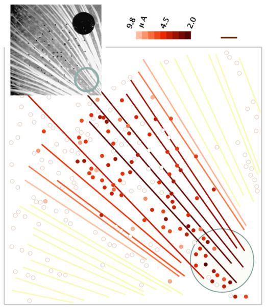
Fig. 7.
Threshold map showing a streak of antidromic stimulation from a 200-μm electrode (blue outline), 400-μs pulse width. Color indicates threshold current. Small black dots are 10-μm electrodes. Scale bar 50 μm. (For interpretation of the references to colour in this figure legend, the reader is referred to the web version of the article.)

