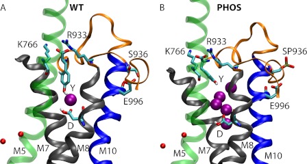
FIGURE 4.
Simulations snapshots showing the entry of water between helices M5, M7, and M8 for the (A) WT and (B) PHOS simulation at 55 ns. Water molecules within 8 Å of Asp926 and within the M5-M7-M8 cavity are shown as purple spheres. K+ ions are shown as small red spheres. Y and D refer to residues Tyr1016 and Asp926, respectively. Helices M5, M7, M8, and M10 are shown in transparent green, black, black and blue, respectively. The loop connecting M8 and M9, and the last 13 C-terminal residues are shown as orange ribbons. A larger number of water molecules populate the cavity between M5, M7, and M8 in the PHOS simulation. Please refer to supplemental Movies 1, 2, and 3 for dynamics of entry of water molecules.

