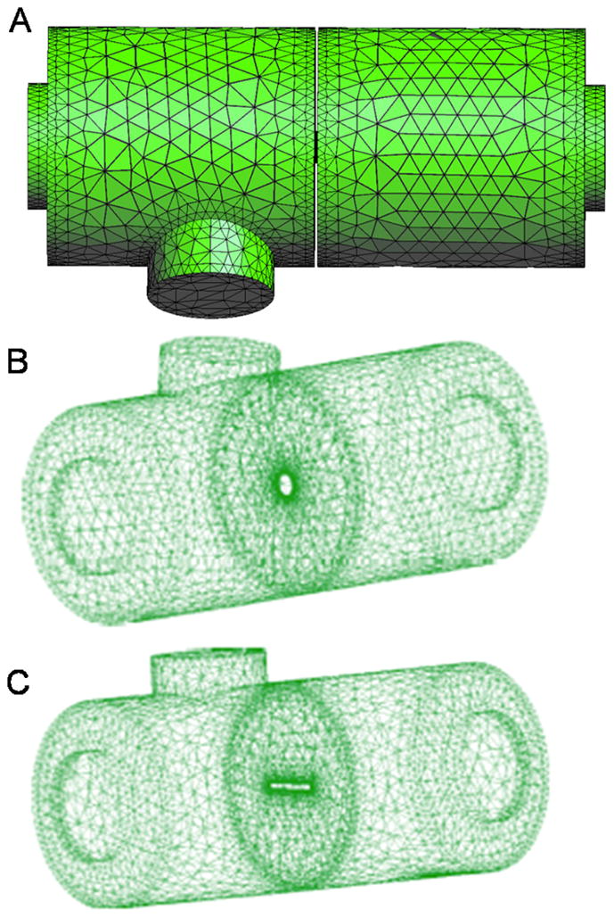
Figure 2.

Computational geometry for the CFD simulations. A) A coarse version of actual meshes is shown. B) Geometry with circular orifice. C) Geometry with rectangular orifice. Unstructured (non-uniform) meshes were used in all the simulations to capture the fine flow structures of flow in complex geometries.
