Figure 3.

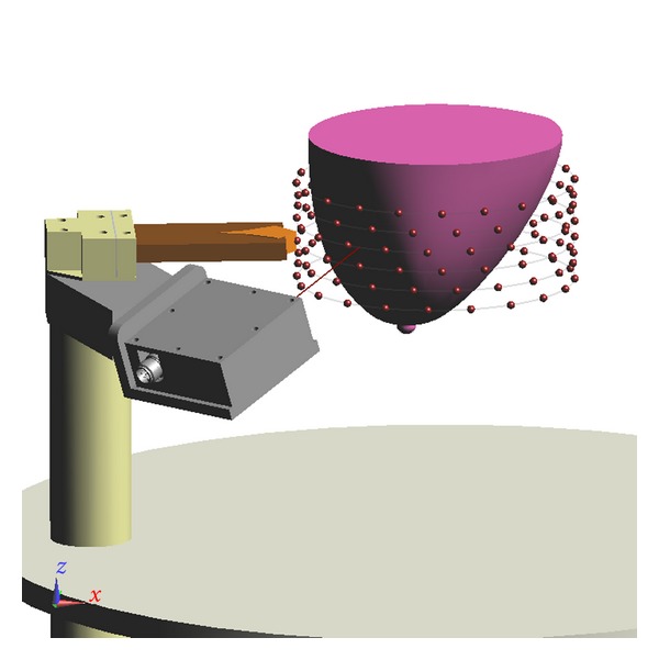
View of the scan pattern used for measurement. Each sphere corresponds to an antenna location. Antennas located on a common row are connected by lines.

View of the scan pattern used for measurement. Each sphere corresponds to an antenna location. Antennas located on a common row are connected by lines.