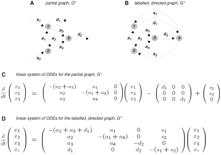
Figure 4. Synthesis and degradation.
A. The non-strongly connected graph in Figure 2A is augmented with partial edges denoting synthesis and degradation to form the partial graph  B. By introducing a new vertex,
  , the partial graph
  is transformed into the labelled, directed graph,
  , which, in this case, is strongly connected. C. The linear system of ODEs arising from the partial graph
  . D. The Laplacian dynamics defined by the graph
  . Since, in this case,
  is strongly connected, the MTT can be applied to calculate the unique steady state of
  , as given in equation (23). The details of the calculation are given in Supporting Information S1.

