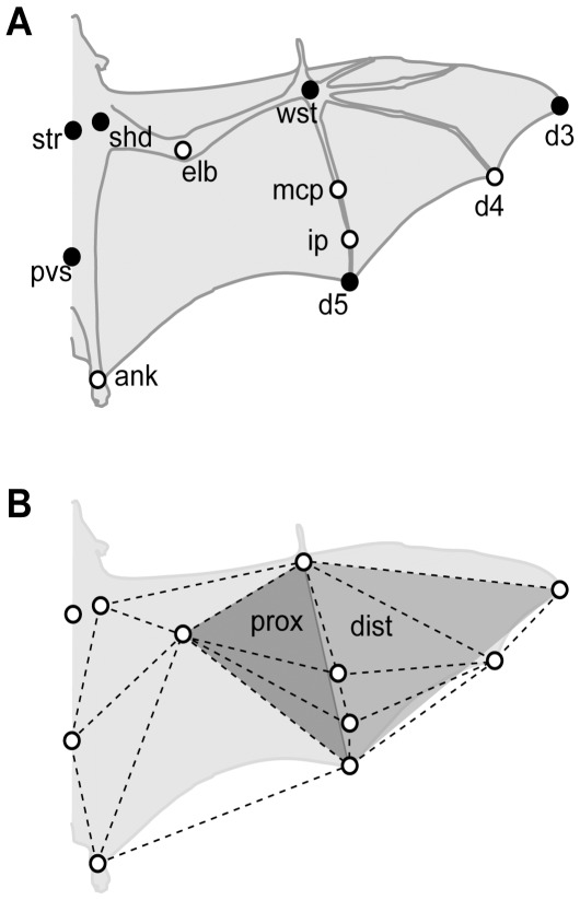
Figure 1. Markers and segmentation used in this study.
Ventral view diagram of a bat indicating (A) the position of the wing and body markers and (B) the triangular segmentation used to calculate surface area, vertical force coefficient (C v), and angles of attack. The dotted lines indicate the 11 segments used to calculate surface area and C v and the grey-shaded triangles represent the segmentation used to calculate the proximal (prox) and distal (dist) angles of attack. ank, ankle; d3, d4 and d5, distal end of of distal phalanx of digits III, IV and V, respectively; ip, interphalangeal joint of digit V; mcp, metacarpal-phalangeal joint of digit V; pvs, pelvis; shd, shoulder; str, sternum; wst, wrist. Black markers indicate the markers used in the flight corridor trials.

