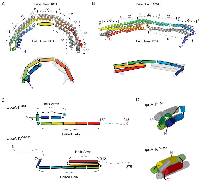
Figure 7.
Structural comparison of apoA-I1-184 and apoA-IV64-335. (A–B) Ribbon (top) and schematic (bottom) representation of apoA-I1-184(A) and apoA-IV64-335(B) in their dimeric forms, each with one chain colored in rainbow from N to C terminus. Both structures reveal two long paired helices with anti-parallel orientation spanning similar distances and punctuated by proline residues. The cross chain aligned proline residues (represented as P) divide the long anti-parallel helix into two 18 and three 22 a.a paired helix regions for apoA-I1-182 and five 22 a.a paired helix regions for apoA-IV64-335. The length of the helical arms is shown, with the central cavity depicted as a yellow oval. (C) Schematic representation of both structures linearly aligned at the paired helix segment. Note the flipped orientation of the helix arm region in relation to the paired helix segment. (D) Schematic view looking down the bundle showing different linkage from the helical arms to the paired helices and how the four-helix bundle is capped in each structure.

