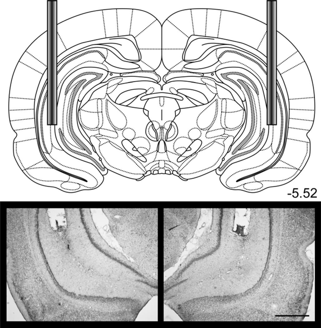
Figure 11.
Bilateral cannulae were implanted in the VH for Experiment 5. The diagram shows the placement of cannulae in the VH. Photomicrograph images show an example placement of the bilateral cannulae. See Figure S5 for individual placements. Scale bar = 1 mm. Diagrams were adapted from Paxinos & Watson, 2007.

