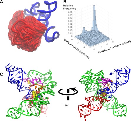
FIGURE 6.
(A) Superposition of models generated from MC-sym sampling for hybrid construct—3P1_10AT. The region shown in blue is from the crystal structure of the yitJ SAM-I riboswitch (PDB:3NPB) (Lu et al. 2010). The part in red is the AT helix as it appears in multiple models generated from MC-sym, with a superposition based upon the fixed region in blue. (B) A two-dimensional histogram of the vdW interaction energies between the nucleobase of U107 and that of A108 and between the nucleobase of A1 and that of U132. A more negative value of vdW energy here indicates better stacking between the nucleobases. (C) An example of models sampling the coaxial helical stacking between the partial P1 and the AT helix with SAM docked into the binding pocket based on the binding mode observed in the aptamer crystal structure. SAM is shown in vdW representation with carbon colored in yellow. The partial P1, J4/1, and P4 helix are shown in blue, J1/2 in orange, J3/4 in magenta, and P2 and P3 in green. The modeling shows that a partial AT helix can stack upon a partial P1 helix without necessarily producing a steric clash with other segments of the structure based upon the aptamer X-ray coordinates.

