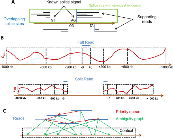
Figure 3.
Resolution of ambiguities. A) Among overlapping splice sites, the one with the best evidence is chosen. Here, two potential splice sites are shown (blue) with distance less than the read length. Evidence is provided by reads supporting the splice site (black lines) as well as known splice signals. In this example, the left-most splice site has more reads supporting it (4 compared for 2 for the right-most splice site) as well as the canonical splice signal GTAG. Thus, this splice site is chosen and the other one is discarded. B) For ambiguous mappings of the same read within a context, coverage scores are calculated based on the number of reads mapping per position (cm, red curves) within the read alignment region and increasingly large windows around the read alignment. Here, -0 indicates the aligned position of the read start and +0 the position of the read end. A negative sign indicates positions upstream of the alignment and a positive sign positions downstream. Region 1 includes the positions from -200 to -0 and +0 to +200 bp, region 2 the positions from -500 to -200 and +200 to +500 bp, and so on. For split alignments only aligned read positions as well as positions upstream of the read start and downstream of the read end are included in the coverage calculation. (C) For the final ambiguity resolution for each context, reads (blue) are connected in a graph (green) to all possible locations in the context they can be mapped to. Furthermore, a priority queue (red) is created in which the reads are sorted according to the difference in coverage scores between the best and second-best alignment. Iteratively, the read with the currently largest difference is removed from the queue, its position is fixed for the context and coverage scores in the queue are updated.

