
Figure 1.
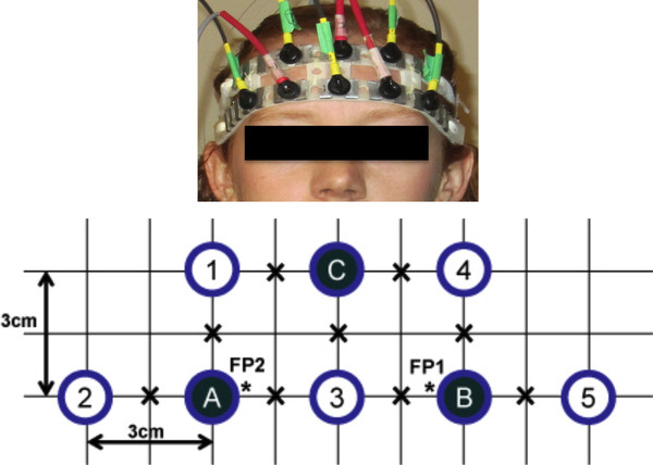
Source-detector configuration. Source-detector configuration. Each open circle represents a source-pair comprising one 690 nm and one 830 nm source fibre, while each solid circle represents a detector. Only the source-pair/detector combinations with a separation of 3 cm were considered. "X" denotes a point of interrogation. "*" denotes the approximate FP1 and FP2 positions of the International 10-20 System.