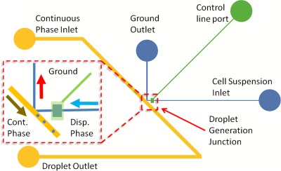
Figure 1.
Schematic of the on-demand droplet generation device. Blue lines indicate the dispersed phase channel, the yellow line represents the continuous phase channel, and the green line is the control channel. Red square denotes the droplet generation region of the device. Inset: The droplet generation area enlarged. The light blue arrow shows the direction of the dispersed phase flow. The red arrow denotes the ground outlet flow direction. The yellow arrow indicates the flow direction of the continuous phase and the flow direction of the generated droplet. Chamber in the fluidic line is visible beneath the green actuation line chamber.

