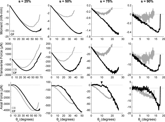
Fig. 12.
Bending moment and forces measured at the base of a C3 vibrissa as it was rotated against a 2D force sensor placed at different radial distances from the vibrissa base. Angle of rotation against the sensor is the push angle, θp. Radial object distance s is indicated as % of vibrissa arc length at top. In all subplots, black traces represent results for a CF collision and light gray traces represent results for a CB collision. Force and moment in all plots stop when the vibrissa slipped off the sensor. Each trace represents the averaged and then filtered result of 25 individual trials. Standard deviation for all trials was ∼10 μN for forces and 0.3 mN-mm for moment. Top: bending moment Mz at the vibrissa base. Middle: Fy at the vibrissa base. Bottom: Fx at the vibrissa base. Arrowhead in the bottom row for s = 75% indicates a typical stick-slip event.

