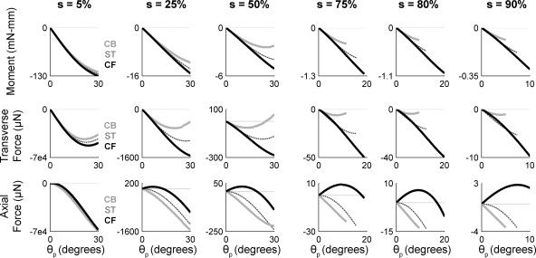
Fig. 9.
Bending moment and forces as a vibrissa is simulated to rotate against a point object placed at different radial distances from the vibrissa base. Angle of rotation into the object is the pushing angle θp. Radial object distance s is indicated as % of vibrissa arc length at top. In all subplots, black traces represent results for a vibrissa with intrinsic curvature undergoing a CF collision, dark gray dashed traces represent results for a straight vibrissa (ST), and light gray traces represent results for a vibrissa with intrinsic curvature undergoing a CB collision. Force and moment traces in all plots stop at the angle at which the simulation became numerically unstable. Top: bending moment (Mz) at the vibrissa base. For all radial distances and all vibrissa curvatures, the magnitude of Mz increases monotonically with rotation angle until contact with the object is lost. Middle: transverse force Fy at the vibrissa base. Bottom: axial force Fx at the vibrissa base.

