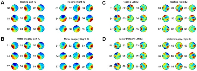
Figure 5. Spatial patterns and spatial filters of the motor components for all nine subjects.
(A) spatial patterns of the resting state; (B) spatial patterns of the motor imagery state; (C) spatial filters of the resting state; (D) spatial filters of the motor imagery state. Black dots in each scalp map indicate positions of C3 and C4 electrodes. In each subfigure, the left and right motor ICs for all subjects were grouped on the left and the right panel respectively.

