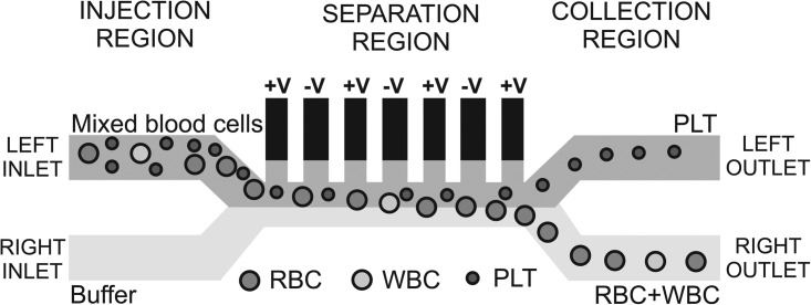
Figure 1.
Schematic of the chip design, showing the different regions and the behavior of the PLTs, RBCs, and WBCs in the system. The microfluidic channels are 40 μm high and 40 μm wide. The dielectrophoretic voltage is applied on the “liquid electrodes” placed on the left side of the channel in the separation region.

