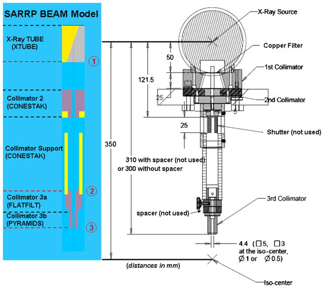
Figure 5.
Right: the SARRP x-ray source and collimator design rendered in the A–B–z plane for the 5 × 5 nozzle. Note that collimator 3 is interchangeable, depending on the desired field size. Left: corresponding SARRP BEAM Monte Carlo model in the G-T–z plane, indicating the types and locations of the incorporated component modules (CMs). The CMs labeled Collimator 3a and 3b differed depending on the field size simulated. A large phase-space file generated at the labeled z-location 1, at the exit of the x-ray tube, was used as input for the second-stage simulations, which incorporated the different choice of Cu filtration. These secondary phase-space files, sampled at z-location 2, were then used as input in the tertiary or final simulations which computed phase-space files at z-location 3; in the final simulations, Collimators 3a and 3b were varied.

