Figure 5.
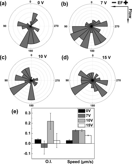
Electrotaxis of activated T cells in the microfluidic device. (a)–(d) Angular histogram of cell migration angles in different dcEF (i.e., 0 V, 7 V, 10 V, and 15 V electrical potential difference between the two electrode wells). The rose diagrams show the distribution of migration angles of all cells analyzed from multiple independent experiments for each condition. The migration angles were calculated from x-y coordinates at the beginning and the end of the cell tracks and were grouped in 20° intervals, with the radius of each wedge indicating the cell number (i.e., the radius of each circle indicates the cell number with the increment of one). (e) O.I. and speed of cells in different applied dcEF. The values are presented as the average ± SEM. The results show the cathode-directing electrotaxis of cells when a 10 V electrical potential difference was applied to the device and thus demonstrate the effectiveness of the developed microfluidic device for analyzing cell electrotaxis in single dcEF.

