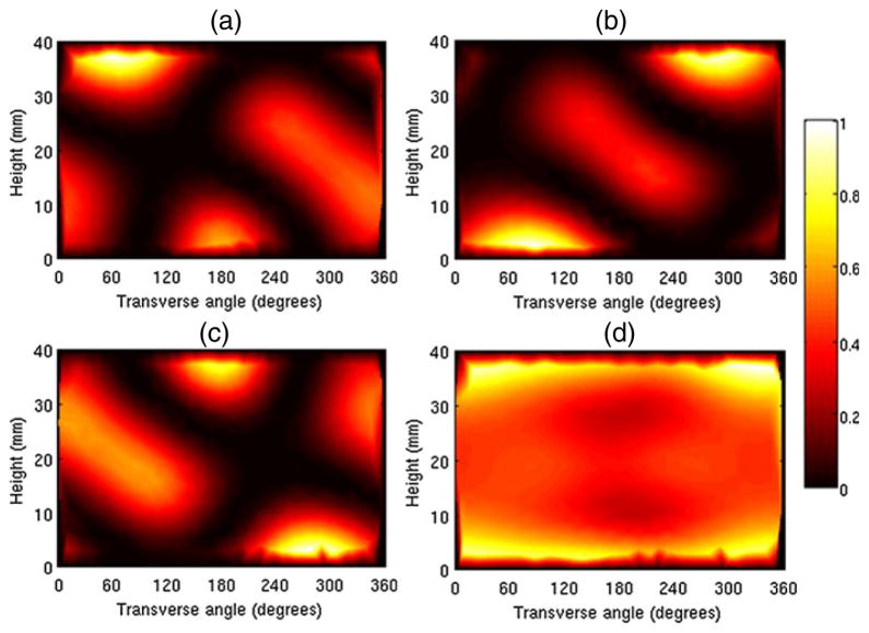
Figure 2.
A set of three optimal patterns on a tessellated cylinder. The individual patterns are displayed in (a), (b), and (c). The sum of the three patterns, displayed in (d), shows rough overall uniformity of illumination. Only the curved surface of the cylinder was used for illumination. For ease of display, this surface is laid out flat so that the vertical axis represents the height of the cylinder and the horizontal axis represents the transverse angle.

