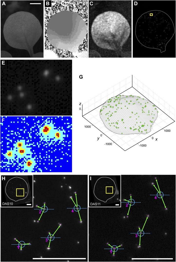
Figure 1.
Acquiring and extracting data. A to D, Leica LAS Montage Module images generated from z-stack images of a leaf. We use the bright-field z-stack to obtain a multifocus montage (A), a depth map (B), and a confidence map for the depth map (C). We use the fluorescence z-stack to obtain a multifocus montage image of the fluorescent particles on the leaf (D). In D, the image is enhanced to improve the visibility of the particles in the publication-sized figure, the leaf outline is plotted for clarity, and the yellow rectangle indicates the region magnified in E and F. Bar in A = 1 mm. E and F, Illustration of the particle digitization algorithm. E shows a zoomed-in region of the fluorescence montage image. The algorithm applies a k-means clustering function that sorts the pixel values into four groups: typically, the dark parts of the image (dark blue), the very faintly glowing areas around the particles (light blue), the brighter glowing areas around the particles (yellow), and the brightest parts of the image, the fluorescent particles (red). The x, y coordinates of particles, shown as green dots, are defined as the centroid of clusters of the brightest pixels (F). G, Digital reconstruction of the leaf surface and particles in three dimensions after extracting z-coordinates from the depth map. Axes units are in μm. H and I, Illustration of the pattern-matching algorithm. We show the particles on a leaf at two successive time points, DAS10 (H) and DAS11 (I). The insets show the fluorescent montage images (rotated so that the leaves are oriented vertically), and the yellow rectangles indicate the areas shown on the main panels. The neighbor patterns of four particles are shown, with the green arrows illustrating the neighbor distances and orientation (measured relative to the axis in blue). Matches between the two time points, indicated by the numbering, are identified by the program based on these unique neighbor patterns. Bars in H and I = 1 mm. For more information, see Supplemental Figure S1.

