FIGURE 5.
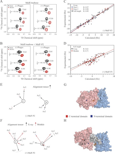
RDC experiments with maltose-bound U-15N,2H MalE in the presence and absence of MalF-P2. A and B, HSQC and TROSY spectra yielding the JNH/2-coupling for selected residues in isotropic (left) and anisotropic (right) buffer for MalE/maltose and MalE/MalF-P2/maltose, respectively. C, experimental and calculated residual dipolar couplings for MalE/maltose and their correlation factors, using the N- (blue) or C-terminal (red) domain or full-length (black) crystal structure of maltose-bound MalE (PDB ID code 1MPD). D, experimental and calculated residual dipolar couplings for MalE/MalF-P2/maltose with respect to the full-length MalE/maltose crystal structure (black) and subsequently to the Module (17)-derived MalE structure. Module uses RDC-derived alignment tensors for individual domains and applies rigid-body modulation to optimize their relative domain orientation. The increased correlation factor in the Module-derived MalE structure from MalE/MalF-P2/maltose RDCs shows that the relative orientation of the individual domains changes in the presence of MalF-P2. E, alignment tensors for the N- and C-terminal domains from MalE/maltose obtained from residual dipolar couplings. F, alignment tensors of the N- and C-terminal domains fitted to the MalE/maltose crystal structure (black) and alignment tensors after correction of the relative domain orientation in Module (red). G and H, surface representation of the MalE/maltose crystal structure and the Module-obtained MalE in the MalE/MalF-P2/maltose complex. The N- and C-terminal domains and their center-of-masses are indicated as blue spheres for the MalE/maltose structure (G). The corrected center-of-mass C-terminal domain is represented by a red sphere (H). Changes in center-of-mass distances from the reference domain orientation to the corrected relative orientation are marked with black dashed lines. Maltose is represented in stick model (orange) in the binding pocket.

