
Figure 1.
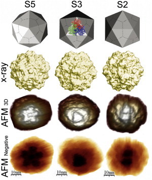
AFM imaging of MVM. (Top) Geometric model of the MVM capsid. In the central image, a ribbon diagram of a trimeric capsomer is superimposed. (Second row) Crystallographic model of the MVM capsid (35,63). (Third row) 3D images obtained by AFM of single MVM capsids. (Bottom) Negative images of the same capsids. Increased height is indicated by lighter (third row) or darker (bottom) tones. Capsids are oriented with an S5, S3, or S2 (left to right) symmetry axis on top (center of the image).