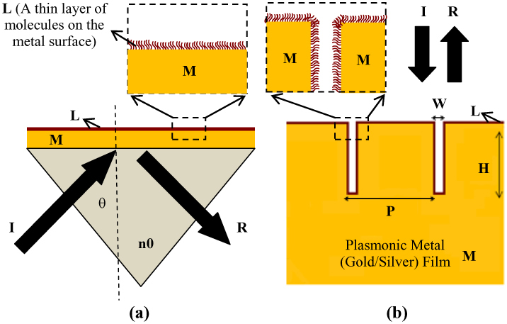
Fig. 1.

(a) Schematic showing Kretschmann configuration conventionally employed for coupling of the incident radiation to surface plasmons and (b) Schematic showing narrow groove plasmonic (gold or silver) nano-grating structure illustrating the important dimensions and parameters. The incident and reflected radiation are indicated by symbols ‘I’ and ‘R’, respectively. While ‘M’ indicates a plasmonic film such as a gold or silver film, ‘L’ indicates a thin layer of molecules on the surface of the metallic film. ‘(P)’ and ‘(H)’ shown in the above figure indicate the periodicity and height of the nanolines in the nano-gratings and ‘(W)’ indicates the spacing between adjacent nanolines in the nano-grating.
