Figure 3.

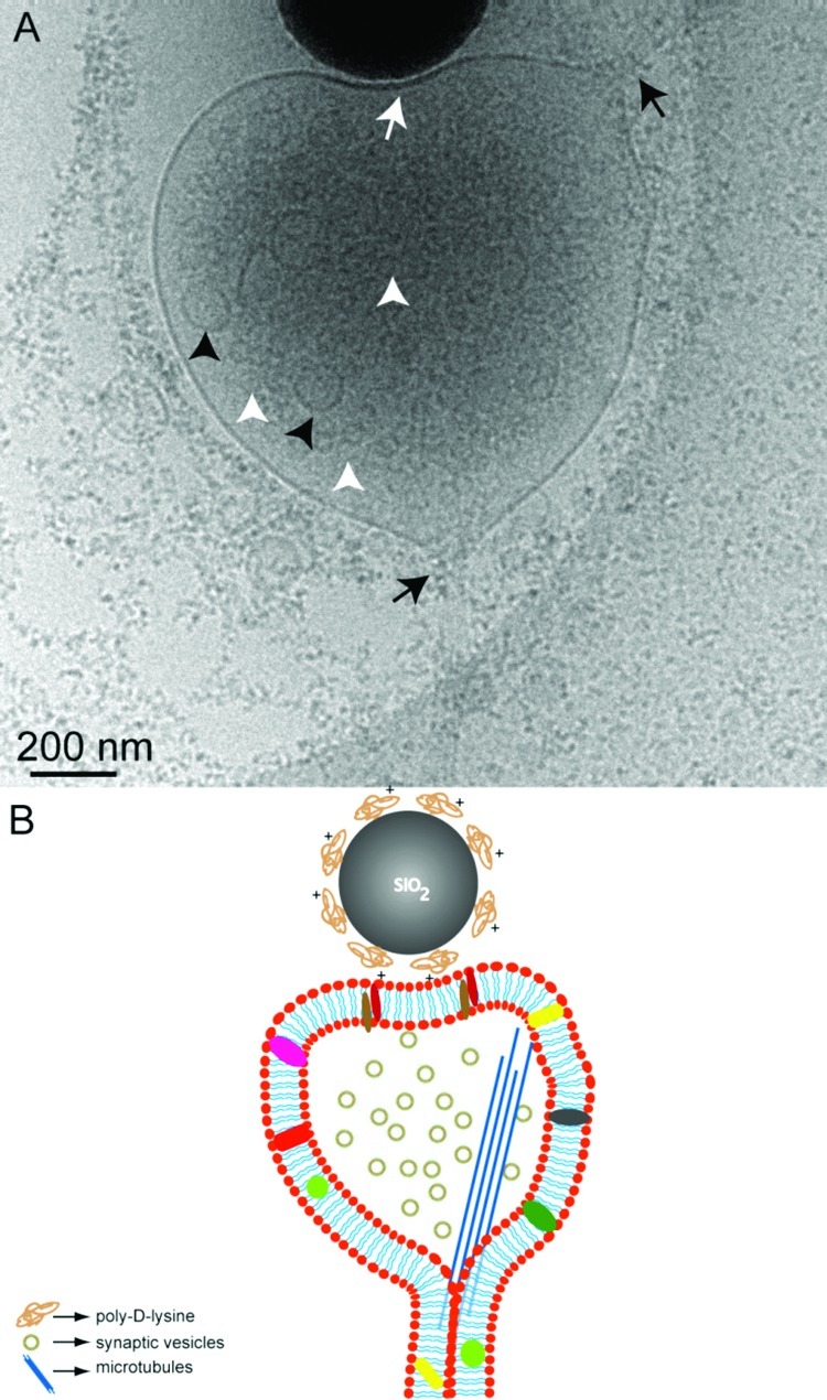
Representative cryo-EM image (A) showing an artificial synapse formed between hippocampal neurons (DIV 8) grown on a sterile, PLL coated Au/Quantifoil grid and poly-d-lysine coated 500 nm silica bead. Only part of the bead is seen in this image. The white arrow indicates the contact area at the synaptic junction. Synaptic vesicles are more clearly visualized (white arrowheads) in this image as compared to Figure 1. The larger vesicles (black arrowheads) could be the transport vesicles. Black arrows show the direction of the axonal shaft growth. (B) Simplified sketch (not to scale) depicting the structural components of the artificial synapse seen in (A).
