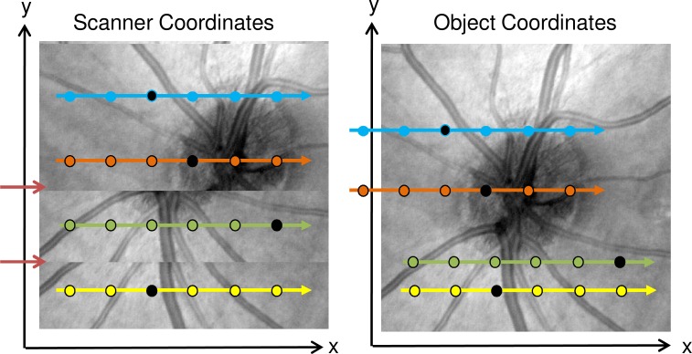
Fig. 3.
Schematic showing relation between object and scanner coordinate system when affected by motion in the transverse plane. Left: En face view in the scanner coordinate system. Dotted arrows indicate B-scans, dots indicate individual A-scans. The background shows an en face fundus projection as it would be acquired given motion. The two red arrows indicate discontinuities from motion. Right: En face view in the object coordinate system. Arrows colored with the same color as left indicate where B-scans from the scanner coordinate system are located in the object coordinate system. The background shows an en face view of the object in the object coordinate system. Individual black dots on each B-Scan indicate corresponding A-Scans in the two coordinate systems. For corresponding A-scans, the position difference in the object and scanner coordinate system is Disp(t) at the corresponding time.

