Fig. 2.

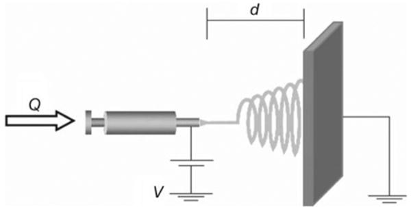
A typical electrospinning setup. Q represents the flow rate and d the distance between the needle tip and patterned plate. V is the applied voltage to control the spinning of the thread (reprinted with permission from [50])

A typical electrospinning setup. Q represents the flow rate and d the distance between the needle tip and patterned plate. V is the applied voltage to control the spinning of the thread (reprinted with permission from [50])