Figure 2.

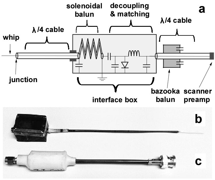
(a) Circuit diagram of the loopless antenna with baluns, decoupling and matching circuitry. (b) Pictures of the 7T loopless antenna, and (c) the quarter-wave length cable with balun (c).

(a) Circuit diagram of the loopless antenna with baluns, decoupling and matching circuitry. (b) Pictures of the 7T loopless antenna, and (c) the quarter-wave length cable with balun (c).