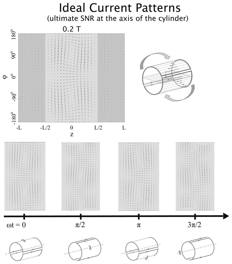
Fig. 7.
Ideal surface current patterns associated with the best possible SNR at a voxel on the axis of a cylindrical sample at 0.2 T. On the left-hand side of the top row, current patterns are plotted for an arbitrary time point on a two-dimensional “unwrapped” view of the cylindrical surface (with the axial and azimuthal coordinates on the horizontal and vertical axis, respectively), whereas on the right-hand side, a schematic representation shows how the current patterns evolve in time. In the middle and bottom rows, the current patterns are shown together with explanatory diagrams for four time points. Ideal currents patterns, which resemble the rotating dual distributed-loop pattern seen in a sphere (Figure 3), may also be recognized as a distributed birdcage-like pattern, in which z-directed “rung” currents vary sinusoidally around the circumference of the cylinder, connected by encircling “end-ring” return currents. The entire current pattern precesses at the Larmor frequency around the axis of the cylinder (i.e. the z-axis).

