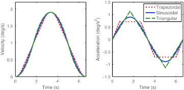
Fig. 1.
Left commanded yaw rotation velocity for the three profile shapes. Right corresponding angular acceleration of the profiles. The profiles were named according to the shape of their acceleration. Note that clearly distinct acceleration profiles have quite similar velocity profiles 95 × 48 mm (300 × 300 DPI)

